

contact@govacons.com.vn

0938 727 179



An overhead crane is often procured as equipment: set capacity and span, select a supplier, then install it. In an existing factory, however, the machine does not stand alone. Wheels load rails; rails load runway beams; beams transfer forces into columns, bracing, bases, foundations and soil. Each interface has limits and tolerances. Adding a crane can require a review of the whole structural system even if the roof and walls look unchanged. This does not mean every crane requires rebuilding: the structure may already suit it, or an independent support may work. The decision must follow actual loads, load path, condition and operation—not visual impressions.
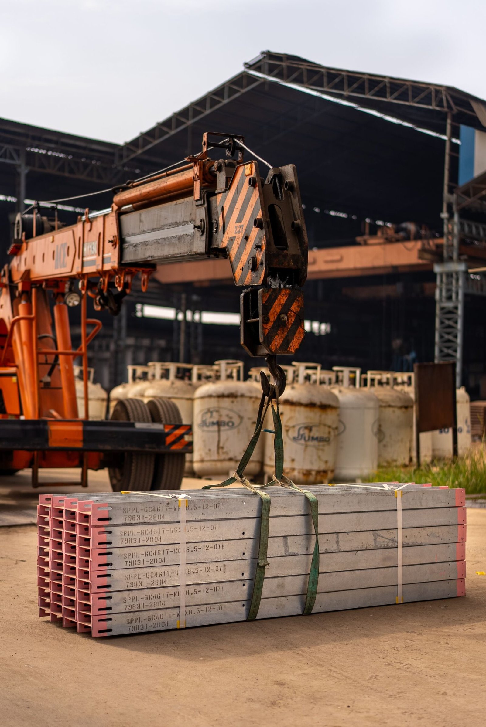
Separate two scopes. The manufacturer designs the crane equipment—bridge, trolley, hoist, travel mechanisms and controls. The building structural engineer designs or assesses the building support. ASCE’s material on buildings with overhead cranes describes this division. An equipment quotation does not verify an existing frame. Coordinate both parties before fixing the configuration.
An overhead bridge crane travels lengthwise while its trolley moves across the bridge. In a top-running arrangement, bridge wheels run on rails atop runway beams. It can serve a broad area, but needs support lines and clearances for bridge, trolley and hook. Single- and double-girder configurations differ in geometry and useful lifting height; neither is universally best.
An underhung crane is suspended from an overhead structure and may preserve space below, but transfers forces differently. Never assume ordinary roof purlins or trusses can serve as a runway. A monorail uses one track for a fixed route, useful for a defined process flow but not the two-direction coverage of a bridge crane. A jib rotates around a freestanding or wall/column-mounted support for a local work cell; it can impose substantial moment on the post, base, anchors, foundation or building frame. Wall-mounted does not mean attachable to any column.
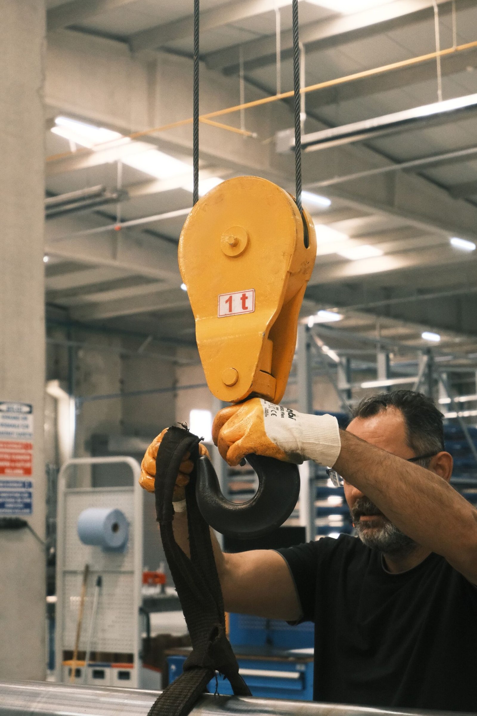
Before selecting, record the heaviest object, lifting attachments, pick/set locations, frequency, travel distance, placement accuracy, speed, waiting time and downtime consequences. “Maximum lift X tonnes” does not distinguish an occasional lift from repeated work every shift. Payload differs from hook block, fixture, magnet, bucket or lifting beam. Forecast machine replacement, product changes, larger dies or heavier material; distinguish approved plans from speculation and define which scenarios belong in the current design.
Map the hook path: must it reach a wall, pass machinery, serve several lines, pass through a door or travel above sensitive areas? Check ducts, pipes, lights, sprinklers, cable trays, platforms and doors. Runway spacing, rail elevation, bridge/trolley depth, lifting travel and end approach define functionality. A crane with sufficient capacity but a hook that cannot reach or descend to the required point is still the wrong choice.
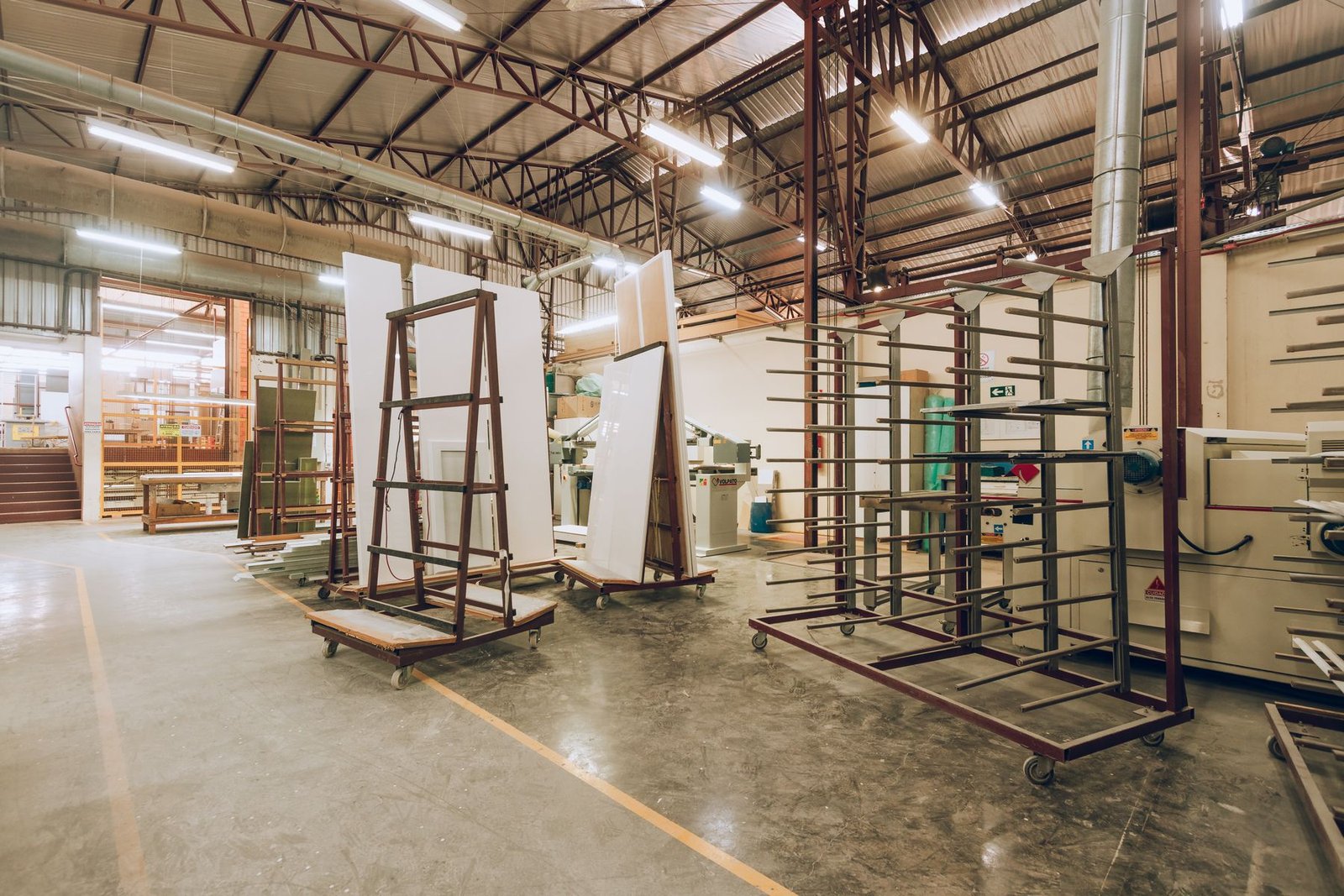
Wheel reactions change with trolley position, bridge position, lifted load and configuration. The engineer needs maximum/minimum wheel loads and spacing, axle spacing, bridge/trolley weights, critical load positions, and manufacturer-confirmed lateral and longitudinal actions. Lifting, braking, acceleration, skew or end-stop contact can create dynamic effects and horizontal forces. Do not multiply catalogue capacity by a rule-of-thumb factor. Use equipment-specific data and combinations appropriate to the project’s Vietnamese design basis.
The load path runs through wheels, rail, clips/pads, runway beam, supports or brackets, columns, bracing, connections, base plates, anchors, foundations and soil. Omitting a link makes “the columns have spare capacity” meaningless. For concrete, establish actual beams/corbels, reinforcement and anchorage; for steel, assess members, connections, stability and the entire load path.
Strength alone is not enough. Beam deflection, column movement, rail-level differences and frame distortion affect alignment, wheel contact, smooth travel, placement accuracy and wear. Limits depend on equipment, span, runway and standards; no single value applies everywhere. Repeated loading also raises fatigue concerns, especially at connections, welds, geometric transitions and rail supports. AISC Engineering Journal material on runway systems addresses cyclic loading, fatigue and crane-specific data. Remaining life cannot be inferred from a member looking straight and uncracked.
Review may include rails/joints, clips, beams, supports, brackets, columns, bracing, connections, bases, anchors, foundations and relevant ground. Consider corrosion, water ingress, forklift impact, cracking, distortion, past repairs and later additions. Foundations cannot be assessed by looking around inside the plant; geotechnical and as-built records and targeted investigation matter.
To avoid confusing lifting capacity with the actions on the building, request wheel reactions and the positions producing them. Reactions can differ when the trolley is near a bridge end rather than at midspan; moving the bridge near a support changes which runway locations are critical. The engineer needs plausible adverse cases, not an isolated maximum without its geometry. If two cranes share a runway, clarify whether they can operate together, their minimum separation and possible load combinations. Do not assume they will always stay apart unless operations can enforce that restriction.
Wheel data also allow the rail and beam to be assessed for their actual role. Rail is more than a rolling surface: rail joints, clips, pads and attachments affect load transfer and alignment. Poorly placed joints, unstable support or elevation mismatch can increase wear and cause rough travel. Rail, clips and runway members must be coordinated with the crane, installation tolerances and maintenance plan; replacing one component without checking its interfaces may not resolve the underlying problem.
Investigation of an existing building should connect directly to the options under consideration. Strengthening a column requires access, new connection locations, cladding interfaces and a verified path to the base. A separate frame requires checking whether foundations conflict with trenches, tanks, utilities or slabs. A gantry requires checking the floor along the whole wheel route, not at one convenient point. A survey that does not answer a decision question can leave the key risk unresolved.
Collect design, fabrication/erection and as-built drawings, calculations, material and geotechnical records, repairs and prior inspections. Compare records with the building: openings, altered connections, suspended equipment and repairs may be undocumented. Missing records are not a reason to guess. The structural engineer identifies whether measurements, connection surveys, opening-up or testing are needed to answer the design question. A strong material sample does not prove that connections, stability, foundations and the full system are suitable.
A competent structural engineer should assess the condition and document scope, assumptions and limits. Visual inspection can reveal signs requiring investigation, but cannot approve a new crane. Large columns do not prove they were designed for crane moments and lateral actions; a new building does not prove future loads were allowed for. Request load data for the exact configuration being purchased. A replacement with the same rated capacity may differ in weight, wheel geometry, speed, duty and reactions.
Set an interface matrix: the supplier issues equipment and load data; the engineer assesses supports, deformation, fatigue and strengthening; the contractor executes the approved work; the owner supplies process information, records and shutdown conditions. Fire, building-services and operations teams join where routes or elevations affect their systems. Put responsibilities in contracts rather than assuming another party checked.
Duty also relates to equipment life and maintenance. A crane may run for few hours but frequently lift near rated capacity, or run longer with lighter loads and smooth movement; operating hours alone do not distinguish these cases. Describe hoisting, lowering, bridge/trolley travel, starts and stops, run times and typical load levels. The supplier uses this to select equipment; the engineer uses operating history and forecast cycles to assess repeated effects on the building. If use changes, update the assessment basis rather than assuming the old crane remains within its former operating envelope.
Stiffness is also an interface between machine and building. Unexpected frame movement can prevent wheels from tracking as intended; a flexible beam can affect travel and hook position. Conversely, increasing stiffness without checking connections and load paths may shift forces into other members. The engineer should consider the overall system, connection conditions, torsion and bracing rather than simply enlarging one beam. Set deformation criteria for the specific equipment and operation, then include them in procurement documents so both parties work to the same basis.
Consider ordinary operations too: will people walk beneath the lifting route, will forklifts cross it, is the set-down area stable, and can maintenance be done without overlapping hazard zones? Equipment layout can change work positions, exclusion zones and procedures. Update operating instructions, training and signs to match the installed system; correct installation alone does not guarantee appropriate use.
Strengthening the existing frame/runway can preserve the layout and avoid a separate system, but first identify the controlling link: beam, bracket, column, bracing, connection, foundation or anchor. Work in an operating plant needs access, lifting, hot-work, dust/vibration, temporary support and shutdown planning. Strengthening a beam does not solve a weak column or foundation.
An independent support frame sends crane loads to new foundations and limits intervention in the old roof frame. It still needs space, foundations, erection access and checks against slabs, buried services, circulation, cladding and fire compartments. It must be stiff and stable, with differential settlement controlled. The benefit is a separate load path; costs include occupied floor area, foundation work, logistics and maintaining adjacent systems.
A mobile gantry or floor-supported device may suit intermittent work or a small area. Check wheel loads on the slab, joints, trenches, levelness and traffic conflicts. Do not assume a floor is adequate because forklifts use it: concentrated loads and wheel arrangements differ. Consider occupied space and keeping a travel corridor clear. Compare lifecycle cost, foundations, access, inspection, spares, downtime and upgrades—not just purchase price or steel weight.
Steel fabrication and heavy machinery may handle bulky items repeatedly; describe stock, assemblies, fixtures, staging, turning limits and traffic. For moulds and dies, machine access, removal clearance, attachments, staging and slow positioning may be decisive. Warehouses must coordinate cranes or monorails with racking, forklifts, loading doors and storage; a crane is not automatically better than a forklift. Light assembly may suit a hoist, jib or mobile device if frequency and load permit.
Wet, corrosive, washdown or food-clean environments can require different materials, coatings, drainage, lubrication, cleanability and contamination controls. Supplier, engineer and operations staff should review actual chemicals, temperature, cleaning and hygiene needs. Coatings do not replace corrosion inspection; clean equipment does not exempt overhead structure from maintenance.
Imagine an operating factory replacing a crane because product and handling have changed. The procurement brief gives only rated capacity; the supplier says the new crane has the same rating and can use the old runway. This anonymized composite illustrates a decision process; it is not a Gova project and asserts no real quantities, duration, savings or outcomes.
The team gathers as-builts, rail configuration, wheel spacing/loads, duty and repair history; the supplier issues data for the actual replacement; the engineer compares records with site conditions and assesses the load path. The plant maps the hook route, affected services and shutdown constraints. Only then does it compare reuse if demonstrated adequate, strengthening identified locations, or a separate support if space, foundations and operations allow. Equal rated capacity does not prove equivalence. Start review before procurement and installation dates are fixed; do not assume every replacement must cost more.
First, prepare the task brief and hook-path map: loads, attachments, frequency, work area, accuracy, environment and credible future cases. Second, have supplier and structural engineer establish configuration, wheel loads, spacing, operating actions, stiffness/deflection needs and interfaces. Third, collect existing records and investigate targeted gaps. Fourth, assess strength, stability, fatigue, deformation, connections, foundations and serviceability. Fifth, compare strengthening, independent frame and floor/gantry alternatives, including shutdown, maintenance and traffic. Finally, confirm current standards and procedures for the project’s location, use, scale and execution date in Vietnam. Foreign guidance does not replace this review.
A crane route may conflict with sprinklers, pipes, lights, detection, cable trays, doors or access. Raising rails or adding a frame can affect clearances, compartments and emergency operation. Coordinate structural, fire-protection, building-services and operations teams during option development. At writing, check consolidated QCVN 06:2022/BXD, record 92/2026/VBHN-TT-BXD, in the Government Gazette and verify all current requirements for the actual project. This article does not prescribe a universal clearance or detail.
Design access for inspection of rails, joints, supports, connections, bracing and wheels; define isolation, safe work methods, inspection schedules and records. Crane and structure maintenance are connected but have different scopes. Avoid oversized equipment and vague allowances by selecting for confirmed work, but do not save money by omitting load data or surveys. Compare equipment, structure, investigation, foundations, installation, downtime, inspection, maintenance, replacement and upgrade costs. Do not claim one option always costs less or cuts carbon without evidence and a defined boundary.
Ask suppliers to document the proposed configuration: crane type, number of girders, span, hook height, trolley positions, bridge/trolley weights, wheel count and spacing, maximum and minimum reactions, lateral/longitudinal actions, speed, duty and braking assumptions. For multiple hooks or attachments, state which load combinations can occur at the same time. Preliminary data should identify open assumptions so the engineer does not mistake an estimate for final information.
The owner must supply information the vendor cannot know: whether lifting accessories are included in the load, operating cycles, acceleration and braking pattern, route, placement accuracy, confirmed future products and daily operating hours. “Continuous duty” is not enough unless it describes lifting rhythm, proportion of heavy lifts, waiting and shift changes. This information shapes both the equipment and the structural load cases.
Check the quotation boundary: are rails, clips, power conductors, end stops, access ladders, maintenance and installation included? Who is responsible for runway tolerances and post-installation survey? Who designs the support system? Unassigned scope commonly becomes a variation or dispute. A clear interface schedule can cost less than resolving responsibility after members have been fabricated.
Two cranes with the same rated capacity can differ in self-weight, wheel count and spacing, bridge stiffness, wheel location, drives and controls. A replacement may shift critical reactions or change acceleration and braking effects. If an old crane served one bay but the new one travels across the factory, cycles and loaded positions change too. Earlier structural findings remain relevant only if the new equipment and use are shown to fall within the assessed conditions.
Even a lighter replacement cannot automatically be called safer. Wheel geometry, hoisting mechanism, speed or frequency may change; runway members and connections still experience repeated actions. Conversely, a higher rated capacity does not mean every reaction grows in the same proportion. Only equipment-specific information permits a meaningful comparison. The engineer should state what was checked, what could not be verified and any operating restrictions that must remain in force.
A structurally sound option may still be impractical if there is no route for members, crane access, lifting clearance, exclusion zone or shutdown window. For strengthening inside the plant, define which operations stop, how areas are protected, how electrical isolation and hot work are controlled, and whether temporary supports are needed. These constraints can change the choice between in-place strengthening and a separate frame; do not leave discovery until contractors arrive.
Removal and installation sequencing also matter. The old crane may need to come out while one runway remains in service, new members may need to be installed in sections, or the replacement may enter through an end wall. Each approach creates different risks for production, people and workmanship. Coordinate procurement with completion of surveys, design, interface approval and site preparation. Ordering before loads are settled can produce a mismatch; delayed coordination can leave equipment waiting for a ready building.
After installation, define required checks before service, who accepts them, which records are handed over and how load changes are controlled. Any temporary operating limitation must be documented and communicated, and removed only with evidence. A safe system requires design, installation, operation and maintenance to use the same confirmed configuration.
At the end of an assessment, owners need an actionable conclusion: which model and records were used, which members and interfaces were checked, what data came from the manufacturer, what site conditions were surveyed, which assumptions remain unverified and what operating limits apply. “The structure was reviewed” is too vague for procurement. If a location is concealed, reinforcement or anchors cannot be confirmed, or records are incomplete, the report should state the limitation and next step instead of assuming adequacy.
Distinguish a conclusion for the assessed configuration from approval for any crane. Restrictions may depend on travel zone, number of cranes, simultaneous operation, lifting load or inspection conditions. If these change, the asset manager should know what information must return to the engineer. Keeping the load schedule with as-builts, equipment manuals and inspection records gives the next upgrade a better basis than an email that merely says “approved.”
Ask for an explanation useful to operations: what can remain in service, what requires strengthening, which areas need construction controls, what must be checked after installation and who maintains it. This does not replace engineering calculations; it carries their results into investment and production decisions. If data gaps prevent a conclusion, compare the cost of further investigation with the consequences of deciding under uncertainty.
Businesses often want to “allow for a larger lift later” to avoid future building work. That can be sensible only when translated into a defined design case: likely equipment type, runway location, load, duty, elevation and production change. Columns or foundations may be considered for a planned expansion, but the provision is meaningful only when the future configuration is defined and documented. An unlimited allowance can add material where it is not needed and still miss the actual future requirement.
Review scenarios with production, maintenance, investment and engineering teams: what is certain soon, what is a distant possibility, and what is only an idea? For confirmed needs, include them now or define a future strengthening step and trigger. For unconfirmed scenarios, avoid paying for unsupported assumptions; preserve information and perhaps space/interfaces for later study, but do not represent that as verified load capacity. This approach controls investment while preserving informed options.
Procurement documents should make the manufacturer’s operating assumptions visible: expected lifting pattern, approach and stopping behavior, control method, environmental conditions and maintenance regime. These assumptions affect how the machine is used and how its reactions are understood. If operating practice changes—for example, heavier lifts become routine or the crane begins serving another bay—the owner should not treat the original assessment as automatically transferable. Record changes and review whether the equipment and supporting structure remain within the documented envelope.
Maintenance planning should include the building interface, not only the hoist and motors. A runway inspection may need access to rail joints, clips, welds, brackets, column attachments and bracing. A repair plan should identify whether the crane must be removed, supported or isolated, and how work can proceed without affecting adjacent production. Early access planning can influence runway elevation, platform placement, lighting and service routes. It can also reveal that an apparently compact layout would make recurring inspection unsafe or impractical.
For a facility manager, a useful handover package connects drawings, load data, tolerances, inspection instructions, maintenance records and operating restrictions. Keep the final equipment configuration and structural assessment together, and identify who controls updates. If a future purchaser or maintenance contractor receives only the crane manual, they may not know the limits of the building support; if they receive only structural drawings, they may lack the actual wheel reactions. The paired record is what makes later decisions traceable.
Procurement schedule is another interface. Site assessment, engineering review, authority checks where applicable, fabrication drawings, long-lead equipment and shutdown planning must fit one sequence. A crane ordered before its runway elevations and clearances are coordinated can arrive with an unusable hook height; strengthening designed after production schedules are fixed can create avoidable disruption. Agree decision gates: what information is required before selecting the model, before releasing fabrication, before site installation and before commissioning. This is project control, not paperwork for its own sake.
Operational alternatives deserve a fair comparison. Forklifts can reach flexible locations but need clear aisles and may introduce traffic conflicts; fixed overhead equipment can keep floor routes open but constrains the lifting zone and needs overhead supports; a jib handles local rotation but has limited reach; a monorail follows a process path but may not serve adjacent stations. The right comparison uses actual flow, load shape, frequency, floor capacity, storage pattern and maintenance capability. No equipment label determines the result without those facts.
For the equipment supplier, the owner’s brief should distinguish routine production from exceptional lifts. A large maintenance lift may occur rarely but still govern access, load path or removable components; normal production may instead govern fatigue and duty. State how loads are attached, whether they can swing, rotate or be positioned with precision, and whether the process requires two hooks or a special lifting beam. These are operational facts, not assumptions the vendor should invent. A clear brief reduces the risk that the selected crane fits a nominal capacity but not the actual handling sequence.
Headroom is a system dimension, not just the roof clearance. The available distance is shared among roof members and services, runway support depth, rail, bridge, trolley, hoist and the hook’s required upper position. The hook must also lower far enough to reach the working height. Raising a runway can improve hook height while affecting cladding, bracing, services, fire systems and building access. Lowering it may simplify supports but reduce useful lift. Review a section through the complete assembly and the real load path before choosing elevations.
Span and approach are equally practical. A bridge can have adequate nominal span but leave an unreachable strip near the wall because of end trucks and building columns. A monorail route may pass the first machine but fail to reach a staging area; a jib may serve one station while its column conflicts with material handling. A plan drawing should plot hook coverage, obstructions, no-go areas and set-down points, while sections verify vertical clearance. This simple spatial check can prevent buying a technically capable machine that misses the critical operation.
Compare strengthening with a separate support on a like-for-like basis. Include engineering, survey, foundations, building alterations, equipment interfaces, temporary works, access, production interruption, inspection and future replacement. A retrofit inside the existing frame may be shorter spatially but more disruptive to install; an independent frame may protect the old structure but consume floor area and create new foundations. A floor-supported alternative may avoid roof work but compete with production routes. The least expensive initial quote may not be the least costly option over the equipment’s working life.
For a new crane building or a major extension, decide early whether the crane is a primary design requirement or a later possibility. If known from the outset, the structural grid, runway elevations, lateral bracing, column bases and foundations can be coordinated around it. If future crane use is only possible, document what is allowed for and what would still require a future assessment. The building should not be marketed internally as “crane-ready” unless the intended equipment envelope and support scope are defined in the design basis.
Fire and building-services review should proceed in parallel with structural options. A new column line can affect access, routes and compartment boundaries; an elevated runway can conflict with detection or suppression components; a maintenance platform can change access arrangements. The correct response depends on the approved fire strategy and the project’s actual configuration. Engage the responsible professionals to assess effects and update coordinated drawings and submissions where required. This article does not prescribe a universal clearance, sprinkler arrangement or fire-compartment detail.
International guidance is useful for recognizing design topics such as fatigue, crane-induced actions, runway alignment and support framing, but it is not a substitute for Vietnamese legal and technical requirements. AISC Design Guide 7 is an international reference for industrial buildings and crane-support design; its own scope and referenced standards differ from Vietnam’s regulatory setting. Use it to inform questions and coordination, not to import a design rule without checking the locally applicable standards and project-specific criteria.
A purchase decision is ready only when three parts align: the crane suits the actual lifting path and duty; the supporting structure and foundations are assessed against equipment data and the existing building; and installation, operation and inspection fit the plant’s conditions. If information is missing, record what is needed, who must confirm it and by when. Rated capacity or a visual impression cannot replace an engineering assessment.
Gova can coordinate advisory, design and construction across legal, structural, building-services and fire-protection interfaces. The crane and support decision itself still needs manufacturer data, an existing-condition survey and assessment by a qualified engineer against the requirements that apply to the building. Coordination helps teams work from a shared basis; it does not replace those technical confirmations.
General guidance only; verify standards and legal requirements for the actual project, location and execution date.


